
To give the board a professional look, and to help prevent solder bridges, I like adding a solder mask. I use a photosensitive dry film mask I bought on eBay, which gets laminated to the PCB, exposed to UV, and developed. This Instructable gives very detailed instructions on the entire procedure.
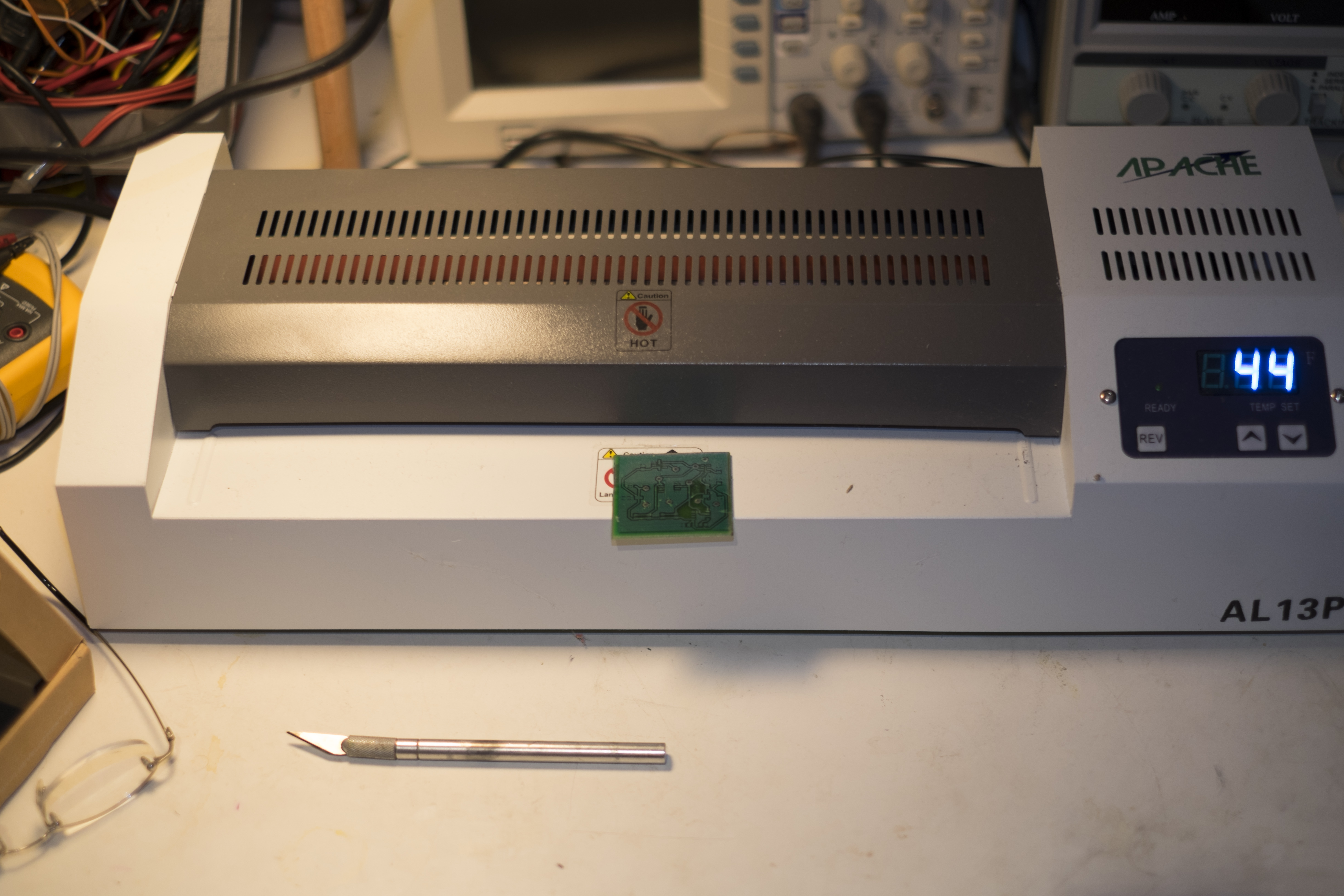
Laminator with PCB ready for development
After the solder mask is developed, I occasionally tin the board. Tinning the board should help protect the copper, and it looks nice, but the tinning solution is expensive, so I don’t do it often. Since this board will be installed outside, though, I decided to give it the full treatment and tin the PCB. I use MG Chemicals 421 Liquid Tin, and it is very easy to use; just pour the liquid into a plastic container with the PCB, and in about 5 minutes, all the exposed copper will have a tin coating.

PCB soaking in the Liquid Tin solution
At this point I’m ready to reflow the components. The hardest part of the whole process is to apply the solder paste. Since I don’t make a solder stencil, I have to apply the paste by hand. I squirt some solder paste onto a card, and thin the paste with some flux so that the paste is only about half as viscous as it was originally. Then I take a toothpick, and gently dab the pads with the thinned paste, making sure I do not put too much paste on the pad; this is one of those cases where less is more. Now it is time to place the components, and I use some good magnifier glasses and an eBay QS-2008 Vacuum Pen, which, for less than $25, works surprisingly well. The PCB and the placed components are then put into my slightly modified Black And Decker Convection Toaster Oven. The only modification I made to was to drill a hole though the interior, and glue a thermocouple in place with QuikSteel high temperature glue. I would love to be able to create an oven controller to have the oven generate the proper temperature profile for the solder paste, but the oven itself cannot heat up quickly enough to match the profile. Right now, I just plugin my multimeter to the thermocouple, crank the oven to maximum, and wait until the temperature hits 215-220 degrees C and turn off the oven. I do wrap the oven in a welder’s blanket to try to increase the insulation, but I think I need to add a couple extra heating elements into the oven, if I want to generate a correct temperature profile.

Reflow Oven with Multimeter Temperature Gauge
The only thing left to complete this PCB is to verify the reflowed solder joints. In this case, the TVS diode had tombstoned a bit and had to be hand soldered. Then hand solder the vias and connector, and the PCB is complete.

Completed PCB
