
I’m working on a project that uses Bluetooth LE to control power outlets. One day, an Amazon special popped up for a set of Etekcity ZAP power control device, and at $20 for 5 power outlet controllers and 2 remotes, I decided to buy just to look at how they worked. The idea is you configure the remote to switch on and off each outlet controller, and I guess you walk around your house with the remote to turn your light on and off. While I don’t really know why you would want to do that, it turned out I really like the form factor of the controller.
 Opening it up, I found some microcontroller that they scraped off the markings, and a 433MHz receiver, just like the ones you can buy from eBay or AliExpress. It also had a 10 Amp relay that did the actual switching, protected by a thermal fuse. It was powered by a transformerless power supply, something I knew little about, except always hearing that they were dangerous and bad.
I decided I could retrofit these units with my Bluetooth module, so I removed the 433MHz receiver, microcontroller, and 5V linear regulator because my project needed 3.3V. I knew from my research on the transformerless AC power supplies that they could not provide much current, so I decided to do some testing to see if it was adequate for my needs.
Hooking up my trusty Maynuo M9711 Electronic Load, I ran the power supply of the device through various current loads, and got the following graph:
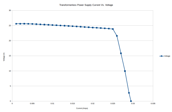
Basically the voltage hangs up around 25 Volts up to about 25mA load, and then it drops off a cliff. Interestingly, once you get past the knee area, backing the current off a little does not cause the power supply to recover. You have to pull the current way back to 15mA or so before the voltage recovers back to its 25V, which means the power supply is not very forgiving of over current situations. Since my BLE module uses about 15mA, and the power supply must also supply current for the relay when it is powered on, just slapping a 3.3 V linear regulator after this power supply would not give a very large margin for error.
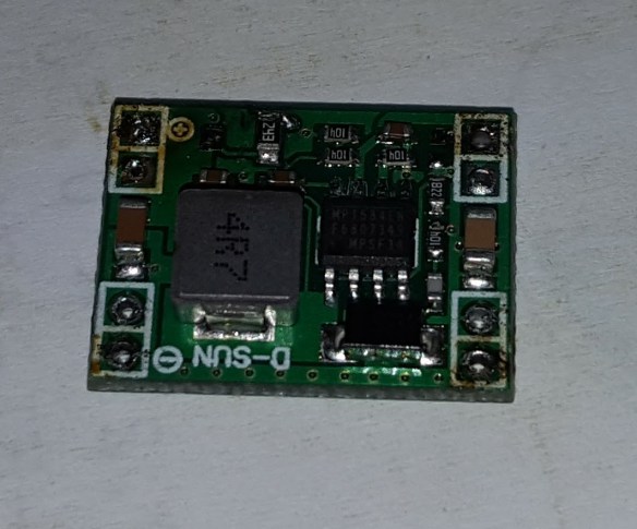
On AliExpress you can find these nifty MP1584 based buck converters that are less than an inch square, and cost less than 50 cents. They come with a really crappy surface mount potentiometer, which really can’t keep a stable setting, so the voltage bounces around a lot. I pulled that pot off and soldered an 0805 24K resistor in its place that fits perfectly in the footprint of the pot, and gives me 3.15 Volts solid. That voltage is right in the middle of the range for the NRF51822 based BLE modules, so that works well.
I tested the load characteristics of the buck converter powered by the transformerless AC power supply, monitoring both the buck converter’s current and voltage, and the transformerless power supply’s current and voltage.

The results are very promising:

The buck converter’s voltage stay constant until the current reaches about 125mA, after which everything falls apart. A current budget of 120mA or so, though, is much more than I will need for my project.
Monitoring both the input voltage and current and output voltage and current of the buck converter allows me to calculate the efficiency of the convert by dividing the output power by the input power. Under these conditions this buck convert was only about 68% efficient, not very good for a dc switching regulator, but good enough for this use case.
